Enclosure Drawing Package Checklist: What to Send a Fabricator
A complete enclosure drawing package has two technical halves: a 3D STEP file that defines the geometry, and a 2D PDF drawing that defines everything the model cannot carry — material, thickness, tolerances, finish, hardware, inspection and packing rules. Add a short commercial sheet with quantity, target lead time and delivery terms, and most fabricators can quote without a single follow-up email. Leave any of it out, and what you get back is an estimate, not a commitment.
That distinction matters because a sheet metal enclosure is rarely just a box. Doors, gasket channels, mounting plates, hinge and latch positions, PEM inserts, cable entry plates, louvers, grounding studs and masking zones all have to be right before the first laser cut. This guide sets out what to send, why each item matters, and the five omissions that most often stall an enclosure RFQ.
What an enclosure drawing package should contain
Use the table below as a pre-send checklist. Every row is something a fabricator has to guess at if you do not state it — and guessing is what produces quotes that change after the first article is built.
| Item | Why the fabricator needs it | What happens if it is missing |
|---|---|---|
| 3D STEP or IGES file | Shows formed shape, bend logic, assembly clearances, internal layout | Bend sequence and interference cannot be reviewed before tooling |
| 2D PDF drawing with revision | Carries material, tolerances, finish, hardware and inspection notes | The legal manufacturing definition is missing; disputes follow |
| Flat pattern DXF or DWG (optional) | Lets the fabricator check bend development and nesting early | Extra back-and-forth before the flat blank is confirmed |
| Calidad del material y espesor de la chapa | Drives bend radius, tooling, weld method, weight and corrosion behavior | Quote is built on an assumed grade that may not suit the site |
| Finish specification, color code, masking | Coating affects fit, corrosion life and cosmetic acceptance | Threads, grounding points and mating faces get coated by default |
| Hardware list (PEM, hinges, latches, studs) | Hardware is purchased or installed against a defined BOM | Quote looks cheaper because hardware was never counted |
| Quantity: prototype plus expected batch | Determines nesting, fixtures and whether tooling pays back | Prototype pricing is quoted where batch economics apply, or vice versa |
| Target lead time and delivery terms | Sets production slotting and material purchasing | A technically correct quote arrives too late to be usable |
| Inspection and document requirements | Dimensional reports, material certificates, CoC, traceability | Documents cannot be retro-issued once parts have shipped |
| Packing and labelling rules | Finished faces and long panels need protection in transit | Coated surfaces arrive scuffed; a good part gets rejected |
Why you need both a 3D model and a 2D drawing
Sending only one of the two is the single most common cause of a slow enclosure quote. They answer different questions.
The 3D STEP file answers “what does it look like”
A STEP file lets the fabricator see overall form, bend structure, how panels relate to each other, internal mounting space, door swing clearance and probable interference points. It is the input for a design-for-manufacture review: bend feasibility, tool access, weld sequence and whether the assembly can actually be put together in the order you drew it. A model alone is enough for a rough budget discussion, but not for production pricing.
The 2D PDF drawing answers “how should it be made”
The PDF is the manufacturing definition. It carries material grade, sheet thickness, critical dimensions and datums, tolerance notes, weld symbols, surface finish and color, hardware callouts, masking zones, inspection points and any special requirement such as grain direction on brushed stainless. When the model and the drawing disagree, the drawing wins — which is exactly why both must carry the same revision number.
Keep them aligned. A revision mismatch between the STEP file and the PDF is one of the fastest ways to get a batch of parts that match one document and fail the other.
How to specify material, thickness and finish
Writing “steel” or “stainless” on a drawing is not a specification. Name the grade, the thickness, and the finish — and say which surfaces are cosmetic, because that determines how much grinding and handling care the job needs.
| Material | Typical enclosure use | Specify carefully |
|---|---|---|
| Cold-rolled / mild steel | Indoor control cabinets, powder-coated boxes, mounting plates | Needs a corrosion finish; bare steel will rust in transit |
| Galvanized steel | Electrical cabinets, telecom housings, semi-outdoor use | Welding and grinding break the coating at the seam |
| Stainless 304 / 316 | Food, washdown, coastal and chemical environments | Grade choice drives cost; chloride exposure is the deciding factor |
| Aluminum 5052 / 6061 | Weight-sensitive housings, heat spreading, anodized finishes | Bend radius requirements are larger than for steel |
Most enclosure shells sit in the 0.8–3.0 mm band, with 1.2–2.0 mm covering a large share of control and instrument housings. Thinner sheet is cheaper to cut but oils-cans on large doors; thicker sheet raises press brake tonnage and widens the minimum bend radius. If you are choosing between grades, the differences between 304 and 316 stainless steel matter more for corrosion life than for strength, and cerramientos de aluminio trade some impact resistance for weight and thermal behavior.
On finish, name the process, the color reference (RAL or equivalent), the gloss level, and any masking. Powder coating typically builds roughly 60–120 µm per surface, and because it builds on both faces it can close up slots, tabs and threads. State whether fit-critical dimensions are measured before or after coating, and mark every thread, grounding point and bonding surface as no-coat.
Which dimensions and tolerances actually matter
The most expensive drawing in the room is the one that tolerances everything. General tolerances cover most features; call out tight control only where function depends on it — door fit, gasket compression faces, mounting hole patterns, and any interface with a purchased component.
| Característica | Commonly achievable | Note |
|---|---|---|
| Laser-cut profile and holes | Around ±0.1 mm | Usually achievable without special fixturing |
| Single formed bend | Around ±0.1–0.2 mm | Springback varies with grade, thickness and tooling |
| Multiple bends / overall formed size | Around ±0.2–0.5 mm | Tighter control needs datums, fixturing or secondary machining |
| Welded assembly | Around ±0.2 mm and wider | Distortion grows with seam length and thin sheet |
| Door flatness | Around ±0.5 mm with ribs or hems | Flatness on large doors needs stiffening, not tighter tolerancing |
These are typical values for general sheet metal work, not a guarantee from any specific shop — always confirm capability against the fabricator’s own equipment. The practical approach is to apply a general tolerance class such as ISO 2768-m to the whole drawing, then add explicit datum-based callouts only on the features that genuinely need them. For geometric control, state the requirement and its datums directly rather than relying on a general-tolerance class alone.
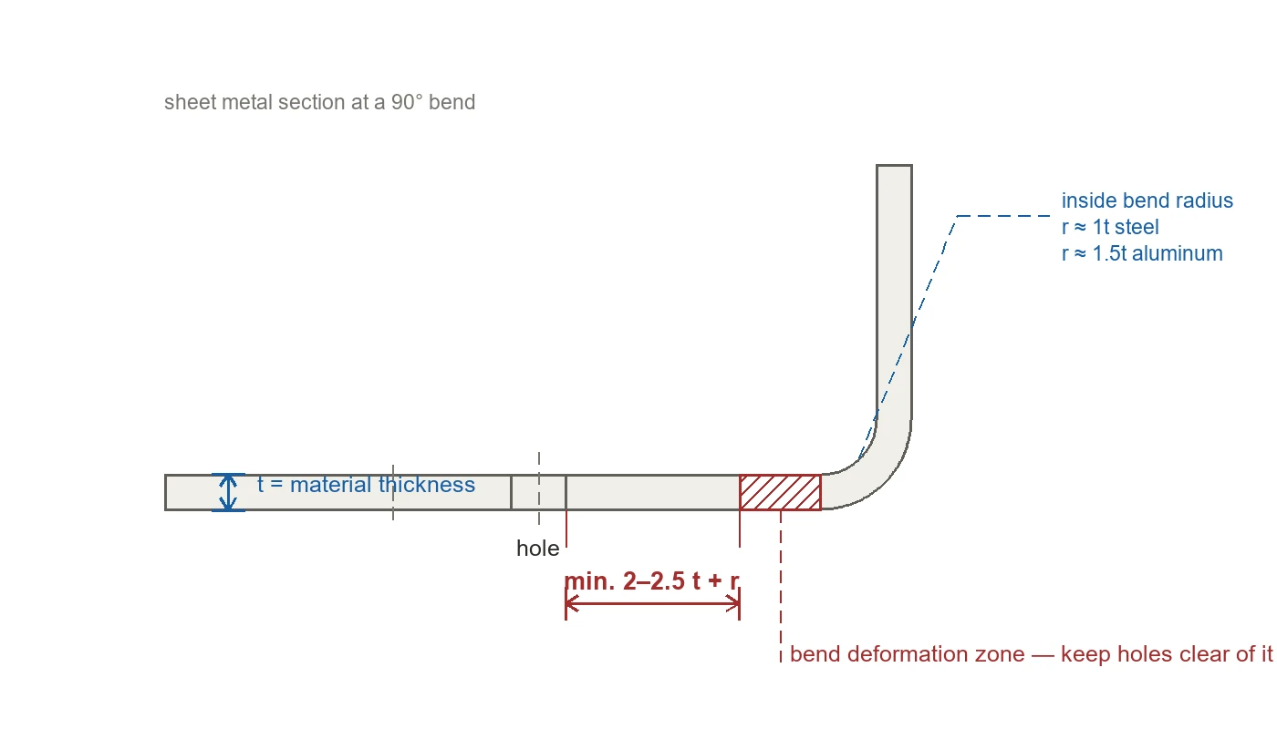
Two geometric rules catch most avoidable rework. First, keep the inside bend radius at or above roughly one times material thickness for steel and around 1.5 times for aluminum — tighter radii risk cracking the outer face, especially on harder tempers. Second, keep holes out of the bend deformation zone: the usual guidance is around two to two and a half times material thickness plus the inside bend radius, measured from the bend line. A hole inside that zone goes oval during forming, and a distorted 4 mm mounting hole is enough to stop an M4 screw seating flush.
How to call out holes, cutouts, hardware and cable entry
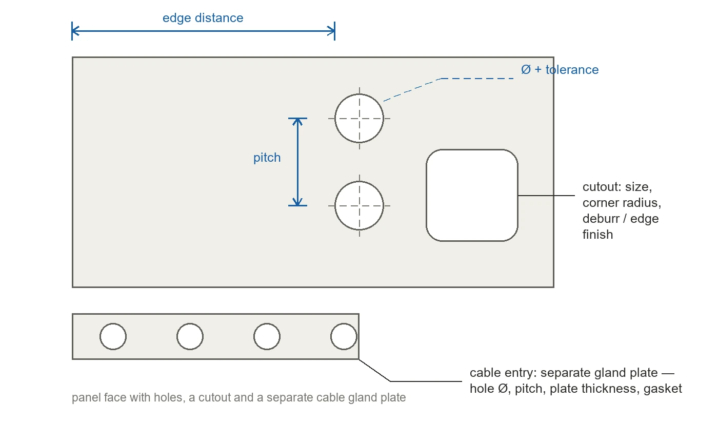
Cutouts are where enclosure drawings most often under-specify. A rectangle on a side panel is not a finished requirement — state the size and position, the edge finish, whether it is laser-cut or punched, and what seals against it.
- Cable entry. Give gland plate dimensions, hole sizes and thread type (metric, PG or NPT), plus the number of ways and spare capacity. A removable gland plate is usually cheaper to modify later than a cutout in the shell.
- Mounting hardware. List every PEM nut, stud, standoff, rivet, hinge and latch with type, size and position. Say whether hardware is installed before or after finishing — it changes both the masking plan and the fit.
- Door hardware. Hinge side, swing angle, latch type, and whether the door must lift off. These decide gasket compression and whether the enclosure can be serviced in place.
- Ventilation. Louvers, perforations or filter fan cutouts, with the free-area requirement if thermal performance is specified. Note that ventilation and a high ingress rating pull in opposite directions.
- Internal interfaces. DIN rail position and length, mounting plate size and thickness, and any bracket or busbar support. These are easy to add at drawing stage and expensive to add later.
For enclosures that house control gear, it helps to think about the internal layout at the same time as the shell — the drawing for a control panel enclosure has to resolve cutouts, mounting plate and cable entry together, not one at a time.
How to specify sealing, grounding and environmental requirements
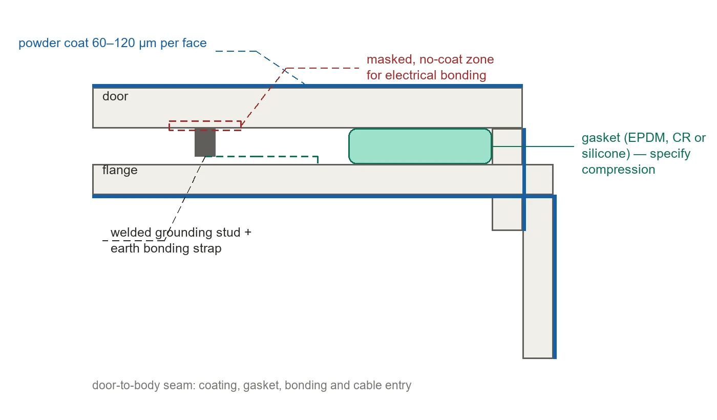
Ingress protection is a design outcome, not a line item. A gasket, a door, a latch pattern and a seam design produce a rating together — you cannot buy it separately.
- State the target rating and the test basis (for example IP65 or IP66 to IEC 60529), and name the surfaces that must stay dry.
- Specify the gasket — material, profile, and the compression the door is designed to deliver. Closed-cell foam, silicone and conductive profiles behave very differently at temperature.
- Mark grounding provisions : stud position, thread size, and every no-coat bonding surface. A grounding point buried under powder coat is a site problem, not a factory problem.
- Describe the environment — indoor, outdoor, washdown, coastal, and any UV or chemical exposure. This is what actually selects material and finish, more than the IP code alone.
If you are working out which rating you need, the differences between IP65 and IP66 ratings come down to water jet pressure rather than dust, and outdoor installations add UV and condensation issues that the IP code does not cover.
What commercial information belongs in the RFQ
Technical files get you an accurate quote. Commercial information gets you a usable one. Put these in the same email as the drawings, not in a follow-up three days later.
- Quantity split. Prototype or first article count, then expected batch size and an annual estimate if you have one. Batch pricing is a different calculation from prototype pricing.
- Target schedule. When you need samples, when you need production, and whether there is a fixed installation date.
- Delivery terms and destination. Incoterms and port or address, because packing and freight can be a meaningful share of landed cost.
- Documentation. Dimensional inspection report, material certificate, certificate of conformity, first article approval — request them now, not after shipment.
- Confidentiality. Say if the drawings are NDA-covered. It costs one line and changes how the files are handled.
One practical note: if some details genuinely are not fixed yet, send the drawing anyway and mark those items “open for review”. A marked gap starts a useful engineering conversation; a missing file starts nothing.
Five drawing mistakes that delay enclosure quotes
- Holes inside the bend zone. They distort during forming and the fit fails at assembly. Move the hole, add relief, or machine it after bending.
- Tolerances tighter than the process. Over-specified non-critical features push the job into fixturing and secondary operations you did not need and did not budget for.
- No masking or grounding callouts. Threads and bonding points arrive coated. Fixing them on site usually voids the finish and sometimes the rating.
- Revision mismatch between model and drawing. Two documents, two revisions, one batch built to the wrong one.
- Finish stated as “powder coated” with no color, gloss or thickness expectation. Cosmetic acceptance then becomes a matter of opinion at goods-in.
Every one of these is cheap to fix on a drawing and expensive to fix on a finished part. A design issue caught before production is a drawing correction; the same issue caught after production is a pallet of parts and a meeting nobody wants.
What happens after you send the package
A competent fabricator will run a design-for-manufacture review before quoting: bend feasibility, hole-to-bend interference, weld distortion risk, coating fit, hardware installation sequence and inspection points. Expect questions, and treat them as a signal that the package is being read properly rather than guessed at.
After review comes quotation, then usually a first article for approval before batch production. Budget time for that first article — it is where door fit, gasket compression and cosmetic finish get confirmed against your drawing. If your requirements are already fixed by project drawings, a supplier that builds custom enclosures manufactured to your drawings removes the on-site modification that usually voids the rating. File formats commonly accepted at this stage include PDF, DWG, DXF and STEP.
The checklist in this article also works as a supplier scorecard: a fabricator who asks about bend radius, masking and inspection documents before quoting is showing you the process you want. That is worth weighting alongside price when evaluating enclosure manufacturers.
Frequently asked questions
Can I get a quote from just a STEP file?
You can get a budget-level indication, because the model shows geometry and bend structure. Production pricing normally needs the 2D drawing for material grade, tolerances, finish, hardware and inspection notes. For serious OEM projects, send both.
What if I only have a sample or photographs?
Photos help open the conversation but cannot confirm material grade, sheet thickness, internal structure, bend radii or hidden mounting details. Expect a reverse-engineering or drawing-preparation step before firm pricing.
How much tolerance detail should I include?
Apply a general tolerance class to the drawing, then add explicit datum-based callouts on door fit, gasket faces, mounting patterns and component interfaces. Tolerancing every feature raises cost without improving function.
Should powder coating be included in the drawing?
Yes — specify process, color reference, gloss, and every masking and no-coat area. Coating builds on both faces of the sheet, so say whether fit-critical dimensions are checked before or after finishing.
What documents should I ask for with the first article?
At minimum a dimensional inspection report against the drawing, plus a material certificate and certificate of conformity if your quality system or end client requires traceability. Ask before production, not after shipment.