How to Size an Electrical Enclosure for a Control Panel
Electrical enclosure sizing starts with the equipment that must fit inside, but it does not end with the width and height of the largest component. A control panel also needs space for mounting, wiring, incoming cables, heat management, door movement and future service. A cabinet that fits the bill of materials on paper can still be difficult to build if these interfaces are left until after fabrication.
The best starting point is a scaled layout of the intended mounting plate and an outline of the installed enclosure. This guide walks through the questions an OEM engineer or panel builder should answer before requesting a standard or custom control panel enclosure.
1. List the components and their installation requirements
Start with the actual component drawings: power supplies, drives, PLCs, breakers, terminal blocks, contactors and any other devices. Record each item’s footprint, depth, mounting method, connection direction and manufacturer’s required spacing. Identify components that need access at the front, such as displays, switches or reset buttons.
Separate the enclosure’s external dimensions from its usable internal mounting space. Door flanges, frame members, a recessed mounting plate and the distance between the plate and closed door can all reduce the usable envelope. A component that is shallow on a catalog page may still need additional depth for wiring or a connector.
| Input to collect | Why it affects enclosure size |
|---|---|
| Component dimensions and orientation | Determines the mounting plate layout |
| Manufacturer spacing requirements | Preserves ventilation and installation clearances |
| Terminal and cable connection direction | Adds room for wire bend and access |
| Equipment heat dissipation | Influences thermal design and accessory space |
| Door-mounted devices | Changes door depth, wiring and swing needs |
| Mounting method and site constraints | Limits allowable cabinet footprint and weight |
Use the component manufacturer’s instructions and the project’s applicable electrical requirements for mandatory clearances. A single percentage allowance cannot replace those specifications.
2. Draw a realistic mounting plate layout
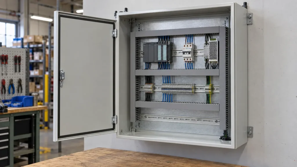
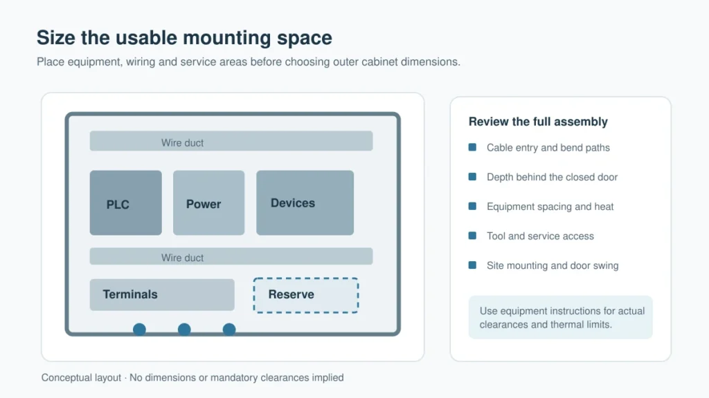
Place the main devices at scale, then add DIN rails, wire ducts, terminals, grounding points and cable routes. Reserve practical space to install and remove parts with tools. Think through the assembly order: a terminal block may be accessible on an empty plate yet hard to service after a large drive is mounted beside it.
Also consider separation requirements defined by the panel designer. Power and control wiring, heat-sensitive electronics and high-heat devices should be laid out according to their equipment instructions and the electrical design. If the layout is crowded before wire ducts are added, the enclosure is probably too small or the internal arrangement needs revision.
Do not use the entire plate edge to edge. Mounting hardware, door seals and cable-entry structures occupy space outside the neat component rectangles shown in a wiring diagram. A drawing with actual footprints will reveal these conflicts early.
3. Check depth and door clearance
Depth is often overlooked because the front view of a panel looks spacious. Measure from the mounting surface to the deepest installed component, then account for plugs, cable bends, covers and the closed door. If controls or a viewing window are installed on the door, include their rear projection and wiring loop.
Confirm that the door can open far enough for maintenance at the actual site. Nearby walls, pipes, adjacent cabinets and handles can restrict the swing. Hinges, locks and a required service aisle may affect whether a single-door, double-door, wall-mounted or floor-standing construction is appropriate.
4. Plan cable entry before choosing the cabinet size
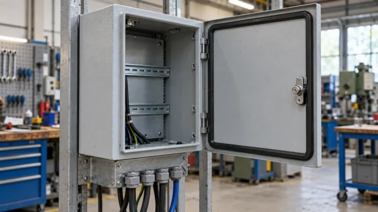
Count incoming and outgoing cables, identify their sizes and decide whether they enter from the bottom, top or side. Allow physical room for cable glands, a removable gland plate if required, bend paths and termination access. Keep entry locations clear of rails, brackets and the door seal.
An enclosure may have enough free volume yet still be impossible to wire neatly if all cables must land in a narrow strip behind equipment. Mark the gland positions and their installation space on the drawing before approving the shell size. For outdoor or washdown applications, review cable entry and sealing together.
5. Evaluate heat and environmental conditions
More internal space does not automatically solve an overheating problem. Add up the equipment’s relevant heat dissipation, identify ambient temperature and sunlight exposure, and determine the allowable internal temperature for sensitive components. Then assess whether passive heat transfer is adequate or whether a designed ventilation or cooling solution is needed.
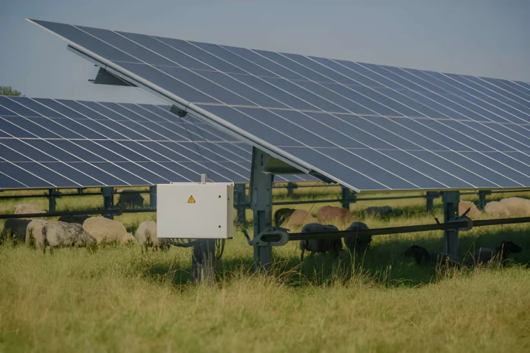
Fans, filters, heat exchangers and cooling units require space, cutouts and maintenance access. Open ventilation can also conflict with a high ingress protection target. If the cabinet will be outdoors, account for humidity, condensation risk and the operating cycle as well as peak temperature. Thermal decisions should be made with the electrical designer before enclosure cutouts are fixed.
6. Decide how much future space is useful
Some projects need spare terminals, an additional DIN rail, extra gland positions or room for a later device. Define the likely expansion rather than adding an arbitrary amount of empty cabinet space. A modest reserved area on the mounting plate may be useful; a larger enclosure can also affect wall loading, transport and installation cost.
If the panel is part of a product line, use the expected future configurations to determine whether one enclosure size can serve multiple versions. Record which areas are reserved and which may be used in the current build.
A simple electrical enclosure sizing workflow
- Collect component data sheets and create a complete bill of materials.
- Place components, terminals, DIN rails and ducts at scale on the mounting plate.
- Check actual usable width, height and depth, plus door-mounted equipment.
- Draw cable-entry positions and installation paths.
- Review heat load, ambient conditions and the target protection level.
- Verify site mounting, door swing and maintenance access.
- Add defined expansion space, then freeze the enclosure drawing for supplier review.
For a custom quote, send both the intended internal layout and the enclosure drawing. A 3D model can show fit and interference, while a 2D drawing can specify material, thickness, cutouts, tolerances and finish. EWJ’s existing enclosure drawing package checklist covers what to include in that handoff.
Conclusión
Good electrical enclosure sizing turns a component list into a buildable, serviceable control panel. Check the real mounting envelope, depth, wiring and heat conditions before choosing outer dimensions. When the equipment layout and enclosure design are reviewed together, there is less need for late cutouts or a larger replacement cabinet.
Designing a custom control panel enclosure? Send EWJ your component layout, mounting requirements and enclosure drawing for a review of the housing dimensions and cutouts.
Preguntas frecuentes
How much extra space should I leave in an electrical enclosure?
There is no universal percentage. Follow the component manufacturers’ spacing and cable requirements, then reserve additional room for installation, maintenance and clearly identified future equipment.
Should I size an enclosure using external or internal dimensions?
Use the usable internal mounting dimensions and depth for equipment layout. Check the external dimensions separately against site mounting and transport constraints.
Does a bigger electrical cabinet eliminate overheating?
Not necessarily. Heat dissipation, ambient conditions, allowable equipment temperature and the selected ventilation or cooling approach must be reviewed together.
What should I include in a custom enclosure sizing request?
Provide component drawings, a mounting layout, cabinet installation constraints, cable-entry positions, target protection level, operating environment and any planned cooling or future expansion.